HMI / Operator Interface Engineering
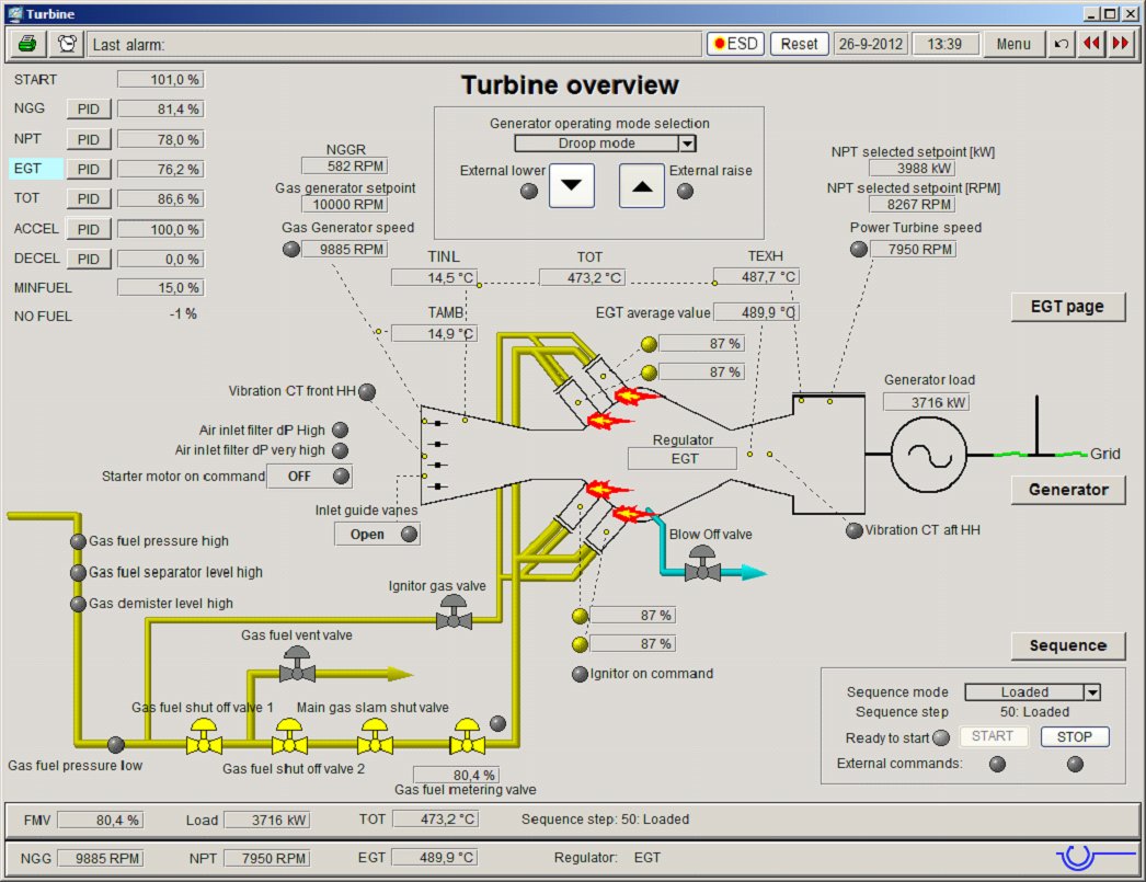
To provide the operator with insight to what is happening with his equipment, we provide an HMI (Human Machine Interface) that is created in conjunction with the software. The HMI functions typically include visualization, command functions such as start, stop or setpoint adjustment. Mostly the HMI is in the form of one (or multiple) stand alone PCs, but they may be mounted in the control cabinet door for example. It is always possible to shutdown (or loose) the HMI, without interruption to the controlling of the controller and the process. Access control to the command features (logging in) prevents unauthorized handling of the equipment, while still allowing viewing of the process.
The HMI screens show the operation of the package systems using information from the control. Each main software module is typically represented on a single HMI page. Typical HMI pages are :
· System overview, a top level view indicating the main system parameters
· Operating sequence including timers and settings
· Trending pages for graphical trending
· Alarm page including alarm and alarm bus filtering
. Alarm annunciation screen
. Alarm history screen
· Sequence of events recorder
. Trending, both historic and real time
· Gas or steam turbine details
· Enclosure and ventilation
· Lubrication oil skids
· Gas and liquid fuel systems
· Liquid fuel forwarding system
· Generator or surge control details
- Command buttons
- starting and stopping of equipment
- raising and lowering setpoints
- acknowledging and resetting alarms
In our design we always include a top and bottom bar that is replicated on each HMI screen to allow the most important information to be present on every screen.


Database advantages for HMI details
One of the advantages of the database tool is that it is an automated process to create items such as an alarm in both the software and the HMI. As a result, even basic applications already hold a very detailed alarm list allowing for very fast identification of a problem.
Customers usually request documentation that contains all details for specific signals such as alarm and ESD levels. However, once the documentation is printed, this information will slowly become more inaccurate as the system is adjusted over time. In other words, alarm values will occasionally be changed from the default values. To counter this problem in our systems, apart from any measured value itself, we also transmit all alarm levels to the operator screen. These are presented to the operator in a small pop-up window containing a small trend of the past few minutes for reference. Should a level be adjusted, it will be visible to the operator at all times without having to check in a paper document or in the software itself.
The default operating language visualized on the HMI screen is English and default engineering units used are SI based. However, different languages and engineering units can easily be made available as an option by using the functionality of the database tools.
If you already have a DCS with all the associated visualization capabilities, we also provide a communications link such as Modbus or OPC through which the relevant data is provided.